Question
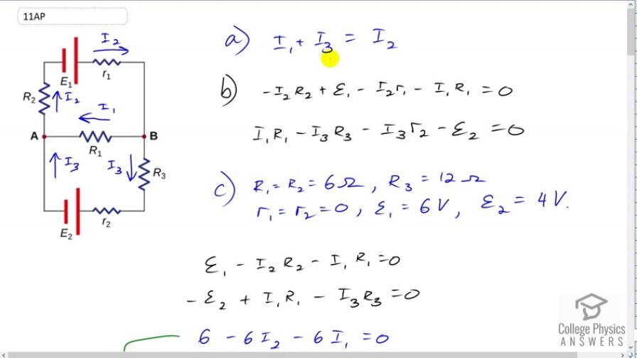
Figure 21.70 In this circuit, assume the currents through , and are , and respectively and all are flowing in the clockwise direction.
- Find the equation obtained by applying Kirchhoff’s junction rule at point A.
- Find the equations obtained by applying Kirchhoff’s loop rule in the upper and lower loops.
- Assume , , , and . Calculate , and .
- For the situation in which is replaced by a closed switch, repeat parts (a) and (b). Using the values for , , , and from part (c) calculate the currents through the three resistors.
- For the circuit in part (d) calculate the output power of the voltage source and across all the resistors. Examine if energy is conserved in the circuit.
- A student implemented the circuit of part (d) in the lab and measured the current though one of the resistors as 0.19 A. According to the results calculated in part (d) identify the resistor(s). Justify any difference in measured and calculated value.
Final Answer
- see video
- , ,
- , ,
- , , ,
Yes, energy is conserved. - The resistor is .
The ammeter introduces additional resistance, , in series with , thereby reducing the current.
Solution video
OpenStax College Physics for AP® Courses, Chapter 21, Problem 11 (Test Prep for AP® Courses)
vote with a rating of
votes with an average rating of
.
Video Transcript
This is College Physics Answers with Shaun Dychko. So fasten your seatbelts ‘coz this question is about seven questions all in one or even more than that, ‘coz some of the questions have sub-questions. But anyway, let’s get her done. So part a says, find the equation obtained by applying Kirchhoff’s Junction Rule at point a. So this junction, we have current three going in and current one going in and current I2 coming out. And so the total going in equals the total coming out. So I1 plus I3 equals I2. And on all of the direction of the currents, by the way. Because we’re told the currents are flowing in the clockwise direction which is this way. And then this way. Then in part b: it says find the equation obtained by applying Kirchhoff’s Loop Rule in the upper and lower loops. So we consider the upper loop first starting at point a. And we’re going to traverse in the clockwise direction. And that means we’re going in the same direction as the current through R2, that means we have a minus I2 times R2. And then we’re going from the negative to the positive terminal of this EMF one. So that’s a positive EMF one. And then minus I2 times little r1. And then minus I1 times little r1. All that equals zero because we end up in point a again. And then for the lower loop, we’ll do point a again. As a starting point we’ll go the clockwise direction in our traversal. But we’re going to begin by going through R1 in the opposite direction to the current. And so we have a positive I1 times capital R1. And then we’ll go down through R3 in the same direction as the currents. So minus I3R3 minus I3 times little r2 minus EMF two because we begin at the positive terminal and end up at the negative terminal. So that makes it a minus there, minus EMF two. We return to point a, and so we say equals zero. And then part c, says assume that we have a bunch of values for all these things in here. And then calculate I1, I2 and I3. We have to solve the circuit. So, R1 and R2 equals zero which is nice ‘coz then they disappear. And EMF one is six. And EMF two is four. And we have R3 is 12 ohms. And R1 and R2 are each six ohms. So we can take this loop rule that we have figured out before. And then get rid of the internal resistance in terms of the little r in them. So EMF one minus I2 capital R2 minus I1 capital R1 equals zero. And this loop becomes EMF two plus I1R1 minus I3R3. And getting rid of that term because it is zero. And then substituting in numbers: EMF one is six Volts, and then R2 is six, and R1 is six. And all that equals zero. Then, EMF two is four Volts. But we have a negative EMF two in our equation. And so we have negative four and then plus six times I1 because R1 is six. Then minus 12 times I3 because I3 is 12 ohms. And this equation becomes I1 plus I2 equals one. After you take the six to the right hand side, which makes it a negative six. So subtract six on both sides. Everything is negative. And then divide both sides by negative six and then you get positive I1 plus I2 equals one. Now, I2 we know is I2 plus I3, because that’s what we know from this Junction Rule. And so we can substitute to replace I2. And so that becomes two I1 plus I3 equals one. And then we can work on this equation here. And simplify it a little bit by dividing by the common factor of two. So we get three I1 minus six I3 minus two equals zero. And now we have two equations with two unknowns I1 and I3. And has a variety of ways to solve that system but what I’ve chosen to do is multiply equation a by three and then subtract from that equation b multiplied by two, because that will target the I1 term and make it disappear because it’s going to become six I1 minus six I1. And we will be having a single equation with only I3 as the unknown which we can solve. So we have six I1 plus three I3 minus two times equation b left side which is three I1 minus six I3 minus two. And then we have three times the right hand side subtracted. So that’s three times one which is three minus two times zero which is zero. So we have just three there on the right hand side. And then distribute this negative two into the bracket. So we have negative six I1 plus 12 I3 plus four equals three. And take this four to right hand side by subtracting it from both sides, you get negative one. And then on the left side, the I1 is sure enough make zero which was the whole purpose of doing this, getting rid of I1. And then three and 12 makes 15 I3. And so I3 then is one over negative 15. Then from equation a, we can solve for I1 and say that it’s one minus I3. And then divide both sides by two. We get I1 one minus I3 over two which is one minus negative one over fifteen times a half which is the same as divided by two multiplying by the reciprocal of the denominator. With fractions within a fraction, I always multiply it with the reciprocal of the denominator whenever it’s about to have a fraction within a fraction. So we have one minus negative one fifteenth times the half so that’s 16 over 15 times a half which is eight over 15. So that’s I1. Then, I2 is I1 plus I3. So that’s eight fifteenth minus one fifteenth which is seven fifteenth. There, that’s part c then. Now in d, we say replace this EMF two by a close switch or a wire. So essentially you draw a black line through in there and I2 is gone. And now do everything again. So we need to find the currents to all three resistors again. So the Junction Rule is still I1 plus I3 is equal to I2 because I1 and I3 is both going to junction a and I2 is the one that comes out of the junction. And then the Loop Rule is going to be for the top loop is going to be negative I2R2 plus EMF one. And then this is zero again. And then, let me go through here and in the middle minus I1R1. And then for the bottom loop, we have positive I1 plus R1 minus I3R3. And there’s nothing on this bottom branch, this R2 is zero and this EMF we are told is gone. And so that’s the end of this Loop Rule here, is that equals zero. Then, replacing the resistances and the EMFs with numbers, the EMF one is six and then minus six times I2 because is R2 is six. And then minus six times I1 because R1 is six. And divide both sides with six and you get one minus I2 minus I1 equals zero. And then working on this equation here, this Loop Rule in green we’re replacing R1 with six and replacing R3 with 12. So it’s six I1 minus 12 I3 equals zero. And that means I1 equals two I3 because you can take this to the right hand side by adding 12 I3 to the both sides. And then divide both sides by six and you solve for I1, two I3. We need to get two equations with two unknowns. And right now we have three equations with three unknowns. We have this one. And we have this one. So we can revisit this equation in blue. Then we place I2 with I1 plus I3. That’s using the Junction Rule, so I2 is replaced by I1 plus I3. And now we have this equation containing the variables I1 and I3. And we have this equation containing I1 and I3. So we can work with that. And so after I2 is replaced with I1 plus I3, this negative gets distributed in there. So that makes one I1 minus I3 minus I1. So the two minus I2 become two minus I1 minus I3 equals zero. Then to get rid of I1, we’re going to multiply equation a by two and add to that equation b. So equation a on the left side multiplied by two and twos become two I1. And on the left side of equation by multiplied by well nothing, just one is going to be one minus two I1 minus I3 and then equals the right hand sides, add it together. And then A is going to be multiplied by two. That makes two times two I3 which is four I3. On the right side of B is just zero, that doesn’t change anything there. Then we have one minus I3 on the left because by design these I1 terms made zero equals four I3. And then add I3 to both sides. And then switch the sides around, you get five I3 equals one and then divide both sides by five. And it makes one fifth. So I3 is one fifth. Now I1 is two times I3, we know from here. And so I1 is going to be two times one fifth which is two fifths. And then I2 is I1 plus I3. So that’s two fifth plus one fifth which is three fifths. Then part e asks us about power dissipation. And so the total power output by the EMF source is going to be six volts times the total current through the EMF. And the total current is this I2. So that’s going to be six Volts times I2 which is three fifths and that makes 18 fifths Watts. And the power through resistor one is going to be the current I1 squared, multiplied by the resistor’s one resistance. So that’s two fifths. I1 is a two fifths here. Two fifths squared times six ohms. And that’s going to be six times four is 24 over 25 Watts. And the power through resistor two is I2 squared times R2. So that’s three fifths squared times six ohms. That makes a nine times six which is 54 over 25 Watts. And then the power through R3 is I3 squared times R3 which is one fifth squared times 12 ohms and because R3 is 12. And that gives 12 over 25 Watts. And then we are meant to check whether or not energy is conserved. So the total power output of the power source is equal to the total power dissipated in the resistors. So the question is, is 18 fifths equal to the 24 twenty fifths plus 54 twenty fifths plus 12 twenty fifths of each resistor. And that makes 90 twenty fifths. And 90 is five time 18 and the denominator is five times five. Five is cancelled giving us 18 over five. And so indeed yes, we see that this total power output of each resistor is indeed equal to the total power output of the voltage source. So energy is conserved. Then in part f, it says a student created the circuit in picture d here. And measure the currents to one of the resistors as 0.19 Amps. And then to which current here is approximately 0.19 and the answer is I3 is one fifth is 0.2. 0.19 is closer to 0.2 than it is to 0.4 or 0.6. And so we conclude that the student is measuring the current I3. So the Ammeter is in here somewhere. Now it’s like less than 0.2 because an Ammeter has internal resistance and by having an additional resistance, it’s going to reduce the current through whatever branch the Ammeter is in. And so we expect it to measure an amount just like and less than with a few radical amount.