Question
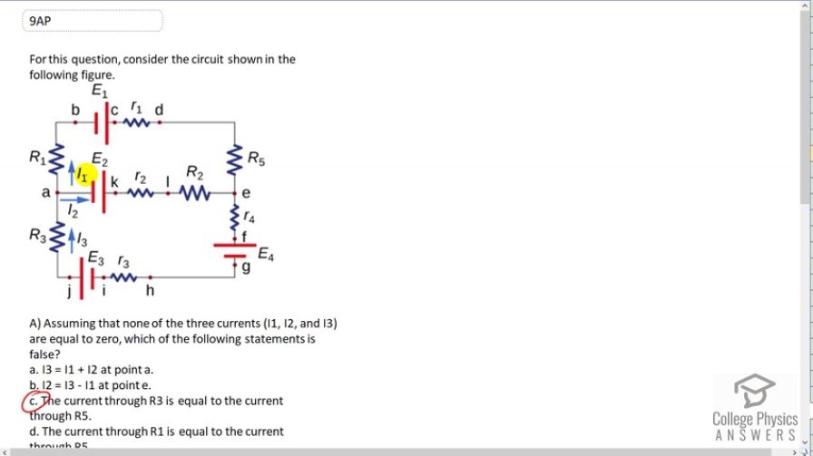
For this question, consider the circuit shown in the following figure.
- Assuming that none of the three currents () are equal to zero, which of the following statements is false?
- The current through is equal to the current through
- The current through is equal to the current through
-
Which of the following statements is true?
-
If and , which of the following statements is false?
- The current through will flow from a to b and well be equal to 5 A.
- The current through will flow from a to j and will be equal to 2 A.
- The current through will flow from d to e and will be equal to 5 A.
- None of the above.
-
If and , will be equal to
- 3 A
- -3 A
- 7 A
- -7 A
Final Answer
(c), (c), (d), (d)
Solution video
OpenStax College Physics for AP® Courses, Chapter 21, Problem 9 (Test Prep for AP® Courses)
vote with a rating of
votes with an average rating of
.
Video Transcript
This is College Physics Answers with Shaun Dychko. We’re given this circuit here and we have a bunch of questions to answer about it. So the first question is assuming that none of the three currents I1,I2 and I3 are zero, which of the following statements is false? So, let’s consider this first statement here: I3 equals I1 plus I2 at point a. And this is true because I3 is a current going in. And the total current coming out is I1 plus I2. And so this is the Junction Rule. At point e, I should say, this is option b, I2 equals I3 minus I1. Well, we have I2 going into this circuit. And we have I3 going down from this side. We have I1 going down this side, as well. So, I2 plus I1 equals I3. And can we rearrange this to make it look like that? Indeed we can. So, I2 is I3 minus I1. And so b is correct. C, the current through R3 is current through R5. So here’s R3 right here. And here’s R5. R5 has a current I1 going through it. And resistor three has a current I3 going through it. And so those are two different currents. Now, there’s some possibility that they, even though they’re labelled differently they could actually be the same. So we have a strong suspicion that c is false but we can’t be perfectly sure until we consider option d. So the current through R1 is the current through R5. Well, that definitely is true because they’re in series. And so we know that d is definitely true. And so c is the only one that has any suspicion of being false. And so that’s going to be our answer. Part B has a whole bunch of gobbily gawk equations here, and the easiest way to figure it out is to just create the loop rule on our own and see which one matches what we created. And there are three different loops to consider. There’s the top loop, the outer loop, and the bottom loop. And the reason that I know to choose the top loop is because all the options here have EMF one and EMF two. And so we should choose a loop which has EMF one and EMF two which is the top loop. So, we begin at point b. And then have a positive EMF one here. So we have EMF one here. And then minus I1 times little r1 and then minus I1 times capital R5 because we’re traversing this loop in the same direction as the current through the resistors so it is always minuses across the resistors. And then, however across this branch right here, down the middle, we’re traversing in the opposite direction to the current through it. And so we have a positive I2 times R2 and then plus I2 times little r2 and then minus EMF two because we are going from the positive to the negative terminal here. And then up through R1 in the same direction as the current. And so we have minus I1 times R1. And all that equals zero. And then I just arranged the EMFs beside each other since that’s the way it’s arranged in all this options here so we can easily compare the two. And it looks like c is what we have written here. EMF one minus EMF two minus I1R1 plus I2R2 minus I1 little r1 plus I2 little r2 plus I1R5. And so there good enough. Option c. Part C. If I1 is five Amps and I3 is negative two Amps, which of the following statements is false? It turns out that none of them is false. So, option a says that the current through R1 will flow from a to b. Well, it says I1 is positive five Amps. And so that means the drawing in our picture is the correct direction for the current because our value is a positive. And so it does indeed flow from a to b. That is the conventional current flows from a to b. And then equal five Amps ‘coz I1 is five Amps. And then option b the current through R3 will flow from a to j and will be equal to positive two Amps. So let’s consider capital R3. It will flow from a to j. It will be equal to two Amps. That is correct because we are told that I3 is negative two Amps. Which means the way it is drawn on our picture is the opposite direction to what the conventional current actuality is. And so the conventional current is in fact going down with a magnitude of two Amps. And so b is correct. And c, the current through R5 will flow from d to e. R5 is here will flow from d to e, and be equal to five Amps. Yes indeed because it’s current I1 which is positive five Amps. And so this drawing is pointing in the correct direction which is down from d to e through R5. And so c is correct. So that’s why none of them are false. And then part D. If I1 is five Amps and I3 is negative two Amps, and I2 will be equal to what? Well, let’s consider a junction somewhere. I use this junction here a. So I3 going into this junction equals the total current coming out which is I1 plus I2. And then rearrange this for I2 by subtracting I1 from both sides. And then switching the sides are on, we got I2 is I3 minus I1. I3 is negative two Amps minus I1 which is five Amps giving us negative seven Amps. And so the answer is d.